SOFTWARE
Powerful and User-Friendly Reverse Engineering Software
Geomagic® Design X™ which is the most comprehensive reverse engineering software of the industry allows you to create CAD data with BOMs starting from 3D scanning. This data can be exported in formats such as STEP, IGES, Parasolid and etc.; it can also create parametric, editable solid models compatible with SOLIDWORKS®, Siemens NX®, Solid Edge®, Autodesk Inventor®, Creo®, and ProENGINEER® miraculously.
You can model your parts quickly and accurately with Geomagic® Design X™, which can work with many devices such as portable measuring arms, laser scanners, optical scanners, area scanners and even computed tomography.
In Geomagic® Design X™ software; there are all drawing commands (line, arc, circle, trim, fillet, mirror, linear pattern, etc.) and surface or solid creation commands (extrude, revolve, loft, sweep, draft, shelf, etc.) found in CAD programs, besides there are also commands (autosurface, mesh fit, etc.) to create more accurate and faster geometries over mesh.


In Geomagic® Design X™ software; there are all drawing commands (line, arc, circle, trim, fillet, mirror, linear pattern, etc.) and surface or solid creation commands (extrude, revolve, loft, sweep, draft, shelf, etc.) found in CAD programs, besides there are also commands (autosurface, mesh fit, etc.) to create more accurate and faster geometries over mesh.
Geomagic® Design X™ has all the tools needed from scanning to modeling during a reverse engineering study. No other CAD software is needed to convert the resulting raster data to solid model or surface.
how it works
- Share with us STL point cloud of the part which was scanned with laser scanner
- We create complete 3D CAD data with using the point cloud
PROCESS

What is Reverse engineering?
The study of design features and/or functional properties of an existing system, device or object also including the manufacturing stages is called reverse engineering.
For what purpose is Reverse Engineering done?
There are 8 main purposes or reasons why we need reverse engineering.
- Copying
- New Part Design
- Desiring to reproduce a product that has not been produced for a long time
- Unable to Reach the Original of the Required Product
- Some Disadvantages of Original Spare Parts
- Requiring Redesign of a Product
- Processing Manual Corrections Made in Parts or Molds into Solid Models
- Reviewing Competitor Products (Benchmark)
How is Reverse Engineering done?
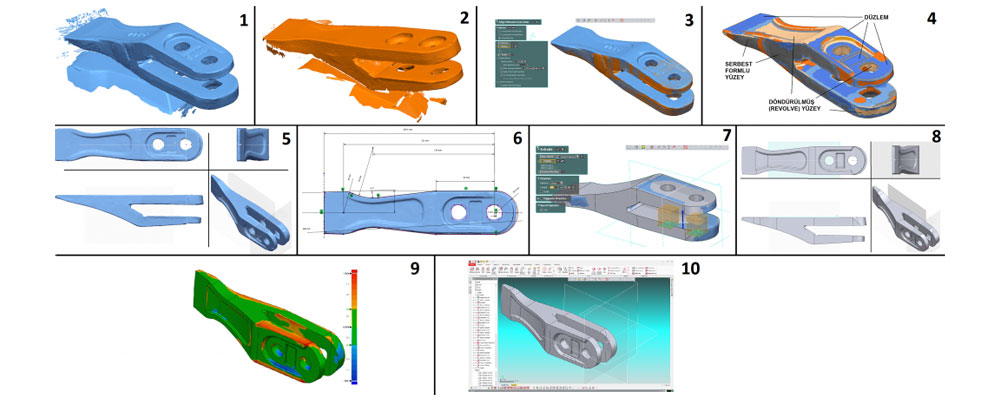
The path to be followed to obtain a 3D model of a part basically consists of 3 main steps.
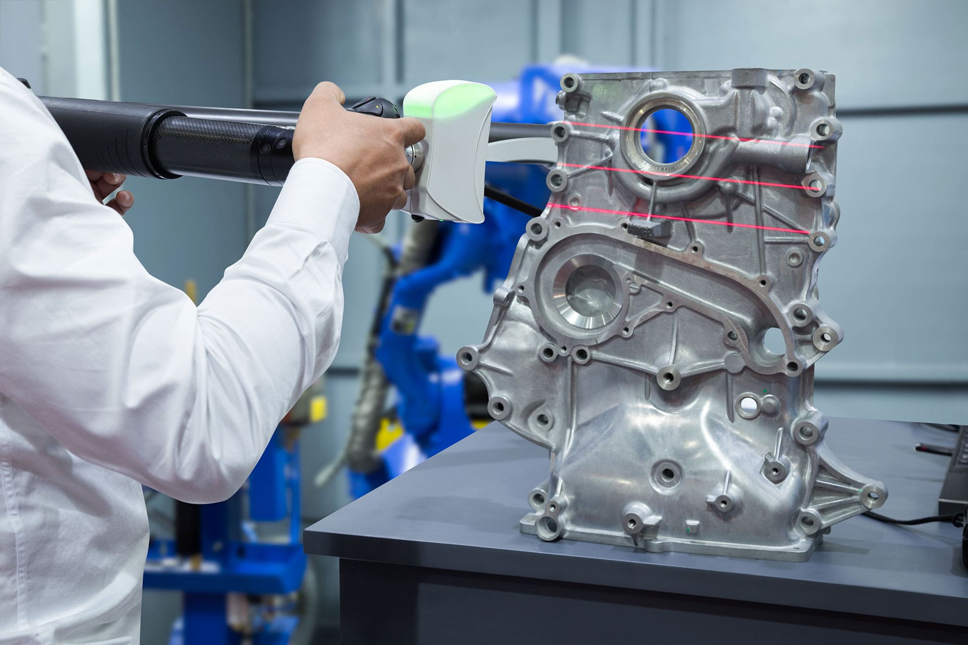
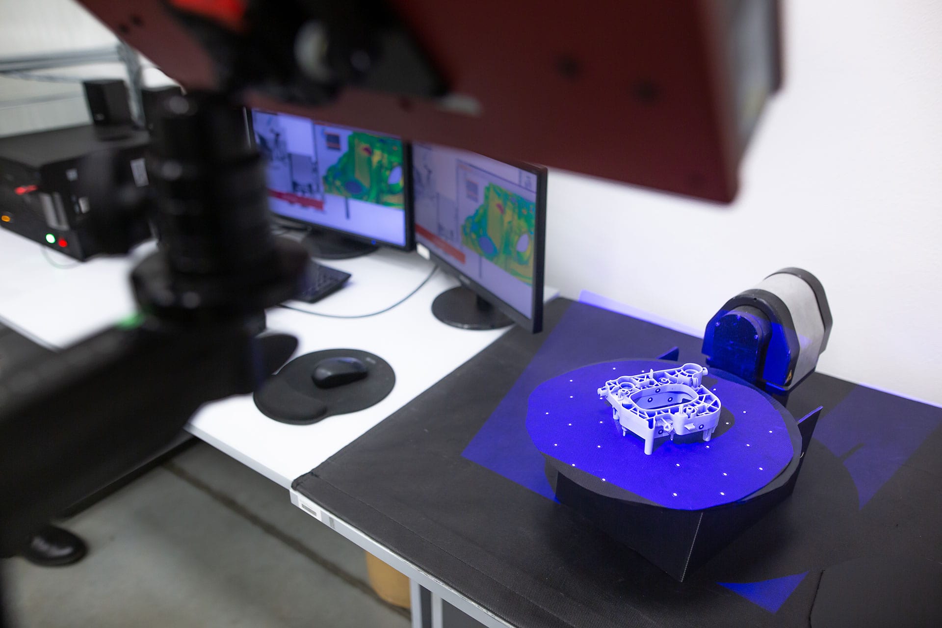
- Taking a Point Cloud: Dimensional point cloud of the part is created with an optical, laser scanner or similar system.
- Conversion to Mesh: Afterwards a mesh is knitted using this point cloud.
- Creating a Solid or Surface Model: In the last step, a 3-dimensional surface or solid model using this network structure; that is, a CAD data is created.
Write Us For More Information


